Solar Charge Controller Sizing Calculator
Calculate the required charge controller amperage rating and verify cold-temperature open-circuit voltage headroom for off-grid and battery backup solar systems.
Tier 1: Array & Battery Sizing Parameters
Sum total nameplate rated power of all solar modules in the array.
Nominal operating voltage of the battery storage bank.
MPPT converts voltage to current; PWM directly switches current.
Illustrative planning buffer, not a universal code requirement.
Typical illustrative engineering margin is 20% to account for cold sunny conditions.
Continuous output rating for 12V DC battery bank
Doubling battery bus voltage cuts charge controller current requirement in half:
Learn how series stringing, cold-weather voltage spikes, and overpaneling limits affect controller choice in our complete Solar Charge Controller Sizing Guide.
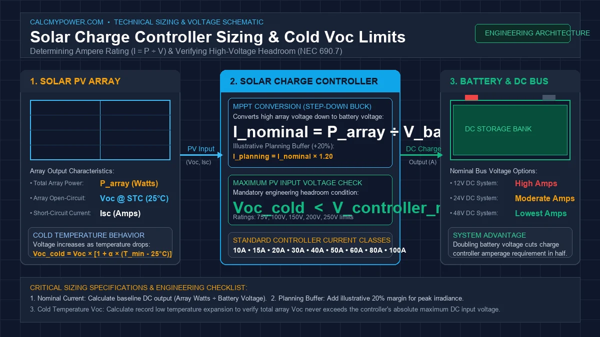
System Power & Sizing Architecture
Visualizing electrical power conversion from the solar array through the charge controller to the battery bank.
Solar Charge Controller Sizing Formulas
The mathematical formulas required to calculate nominal charging current, apply illustrative planning buffers, and verify cold-weather open-circuit voltage headroom.
Variables & Constants
P_array (Watts (W))V_battery (Volts DC (V))I_nominal (Amperes (A))Buffer% (Percent (%))Voc_cold (Volts (V))- MPPT controllers step down high solar array voltage to battery charging voltage, increasing charging amperage proportionally.
- PWM controllers clamp panel voltage down to battery voltage and cannot step down voltage into extra current; size PWM controllers from array short-circuit current (Isc).
- Open-circuit voltage increases as temperature drops below 25°C. Cold Voc must remain strictly below the controller maximum DC input voltage.
- The 20% buffer is an illustrative planning buffer, not a universal code requirement.
Step-by-Step Worked Example: 400W Solar Array on 12V Battery with Cold-Weather Voc Check
Sum the rated peak power of all solar modules in the array under Standard Test Conditions (STC: 1,000 W/m², 25°C cell temperature).
Select the nominal direct-current operating voltage of the battery storage bank (12V, 24V, or 48V DC).
An MPPT charge controller performs step-down DC-to-DC conversion, converting higher PV string voltage down to battery charging voltage while increasing amperage.
An illustrative 20% planning margin accounts for edge-of-cloud irradiance spikes, cool panel operating conditions, and prevents prolonged continuous operation at 100% capacity. This is an illustrative planning buffer, not a universal code requirement.
Select a charge controller with a continuous output rating meeting or exceeding the planning amperage (e.g. 40A, 50A, or 60A class).
As ambient temperature drops, silicon photovoltaic voltage increases. Sizing must verify that the cold-temperature open-circuit voltage never exceeds the charge controller's maximum DC input voltage.
Solar Charge Controller Sizing Assumptions & Variables
Key assumptions and parameters used in calculating solar charge controller amperage, technology selection, and cold-temperature voltage headroom.
| Parameter | Model Default | Typical Field Range | Practical Impact |
|---|---|---|---|
| Nominal vs. Real-World Charging Voltage | 12V, 24V, or 48V Nominal DC | Bulk/absorption charging voltages reach 14.4V (12V bank), 28.8V (24V bank), or 57.6V (48V bank) | The simplified formula uses nominal battery voltage for conservative baseline current sizing. During actual absorption or equalization stages, battery terminal voltage is higher, which causes real-world amperage to be slightly lower for a given wattage. |
| Illustrative Planning Buffer | 20% Margin (Editable: 0% to 100%) | 0% to 25% depending on system design preferences | Photovoltaic panels can occasionally exceed 1,000 W/m² irradiance during cloud-edge reflection phenomena, cold sunny mornings, or high snow-albedo conditions. An illustrative planning buffer provides engineering headroom. It is an illustrative planning buffer, not a universal code requirement. |
| MPPT vs. PWM Conversion Physics | MPPT (Step-down DC-DC buck converter) | MPPT efficiency typically 95% to 98% | PWM limited to array short-circuit current (Isc) | PWM controllers clamp module voltage directly to the battery bus without stepping down voltage into current. Sizing a PWM controller requires knowing the array short-circuit current (Isc) rather than array wattage. |
| Cold-Temperature Open-Circuit Voltage Deration | STC Cell Temp: 25°C | Default Voc Coeff: -0.30%/°C | -0.26%/°C to -0.36%/°C depending on panel silicon specification | Open-circuit voltage increases as temperature drops. Exceeding a charge controller's maximum DC input voltage even for milliseconds can cause irreversible internal semiconductor damage. Always obtain the exact temperature coefficient from your panel datasheet. |
Solar Charge Controller Frequently Asked Questions
How do I calculate what size solar charge controller I need?
What size charge controller do I need for a 400W solar array?
What is the difference between MPPT and PWM charge controllers?
How does battery voltage affect charge controller current?
Why does solar panel voltage increase in cold weather?
How do I check solar panel Voc against a charge controller?
Preliminary Planning & Electrical Engineering Disclaimer
- This tool provides preliminary educational sizing estimates based on user inputs and simplified mathematical models. Real-world solar array power, charging current, and battery absorption rates vary continuously with solar irradiance, module temperature, wiring resistance, and charge controller operational efficiency.
- The default 20% planning buffer is an illustrative planning margin intended to demonstrate conservative sizing headroom. It is an illustrative planning buffer, not a universal code requirement. System designers must consult applicable regional electrical codes (such as NFPA 70 / National Electrical Code Article 690) for mandatory conductor, overcurrent, and disconnect sizing requirements.
- Photovoltaic generation systems and battery energy storage systems operate with high DC voltages and substantial short-circuit fault currents capable of causing electrical fire, severe injury, or property damage. Always verify equipment compatibility against manufacturer specifications and consult a licensed electrician or engineer before purchasing equipment or performing physical installations.
Related Electrical & Solar Calculators
Solar System Size Calculator
Calculate the solar system size in kW and approximate panel count required to power your home based on monthly kWh electricity consumption.
Solar Panels Series vs Parallel Guide
Complete MPPT vs PWM sizing guide covering cold-weather Voc calculations, battery voltage matching, and overpaneling.
Inverter Size Calculator
Calculate continuous and surge wattage, DC battery current draw, cable gauge (AWG), and fuse sizing across 12V, 24V, and 48V systems.
Solar Battery Sizing Calculator
Size your off-grid or hybrid battery bank in Amp-hours and Watt-hours based on daily energy consumption and days of autonomy.
Solar Battery Charging Time Guide
Calculate how long it takes to charge a battery with solar panels. Covers peak sun hours, MPPT vs PWM efficiency, and chemistry absorption stages.
Solar Panels in Series vs Parallel
Understand how series and parallel wiring strings affect array operating voltage, short-circuit current, and charge controller compatibility.
Solar Panel Tilt Angle Calculator
Calculate optimal seasonal tilt angles and compass orientation for your specific latitude to maximize PV generation.
Battery Capacity & Sizing Calculator
Convert battery Amp-hours to Watt-hours, calculate usable storage based on Depth of Discharge, and estimate runtimes.
Watts to Amps Electrical Calculator
Convert real power in Watts to circuit current in Amperes across DC, 120V/240V single-phase, and three-phase circuits.
Voltage Drop Calculator
Calculate circuit voltage drop and size conductors between solar PV arrays, charge controllers, and battery banks.
Solar Charge Controller Sizing: MPPT vs. PWM Formulas & Cold-Weather Voc
Sizing a solar battery charge controller prevents thermal overload, safeguards battery chemistry, and avoids damaging sensitive electronics from winter open-circuit voltage spikes.
Core Mathematical Sizing Formulas
National Electrical Code (NEC Article 690) mandates applying a 125% continuous duty multiplier to solar array current output when sizing controllers and circuit protection:
MPPT (Maximum Power Point Tracking)
Acts as a smart DC-to-DC step-down transformer. It allows high-voltage solar strings (e.g., 80V to 150V Voc) to step down to battery charging voltage (12V, 24V, or 48V) while multiplying charging current proportionally.
- • Delivers 20% to 30% more power during cold weather.
- • Enables smaller gauge wire from roof to controller.
- • Recommended for all solar arrays above 200 Watts.
PWM (Pulse Width Modulation)
Acts as a direct switch connecting the solar panels directly to the battery bank. The panel operating voltage is pulled down to match battery voltage, discarding extra voltage as lost power.
- • Inexpensive for small DIY setups under 200 Watts.
- • Requires solar array nominal voltage to match battery voltage.
- • Inefficient when panel Voc significantly exceeds battery voltage.
Sub-Freezing Voc Limits (NEC Table 690.7 Temperature Factors)
Solar photovoltaic cells produce higher voltage as temperatures drop. Failing to account for sub-freezing winter temperatures will destroy charge controllers by exceeding maximum input voltage ratings:
| Lowest Ambient Temp (°F) | Lowest Ambient Temp (°C) | NEC 690.7 Multiplier | Example: 40V Voc Panel | Minimum Controller Rating (2 in Series) |
|---|---|---|---|---|
| 68°F to 77°F | 20°C to 25°C | 1.00 | 40.0V | 80.0V Input |
| 32°F to 40°F | 0°C to 4°C | 1.10 | 44.0V | 88.0V Input |
| 5°F to 13°F | -15°C to -11°C | 1.16 | 46.4V | 92.8V Input |
| -13°F to -5°F | -25°C to -21°C | 1.20 | 48.0V | 96.0V Input (Use 150V MPPT) |