Three Phase Power Calculator
Calculate real power (kW), apparent power (kVA), reactive power (kVAR), and line current (Amps) for balanced three-phase electrical circuits. Supports line-to-line and line-to-neutral measurements.
Common 3-Phase Equipment Presets
Standard US commercial voltages: 208V, 240V, 480V, 600V (phase-to-phase).
Operating current measured on any single phase conductor in a balanced system.
Ratio of active real power (kW) to apparent power (kVA). Pure resistive loads have PF = 1.0; AC motors typically operate between 0.80 and 0.90.
21,200.30 Watts at 480V (V_LL) with PF 0.85
Polyphase System Metrics
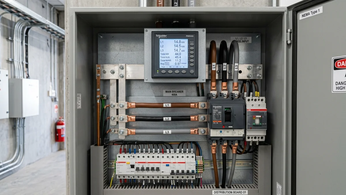
Three-phase distribution panel showing insulated phase conductors (L1, L2, L3) and multi-function digital power metering for commercial active (kW) and apparent (kVA) power measurement.
Three-Phase Power Calculation Methodology
In three-phase alternating current circuits, power is supplied by three alternating voltages separated by 120 electrical degrees. Calculating total power requires accounting for line-to-line vs line-to-neutral voltage references and the load power factor.
Variables & Constants
P (Watts (W) or Kilowatts (kW))S (Volt-Amperes (VA) or kVA)Q (Volt-Amperes Reactive (VAR))V_LL (Volts (V))V_LN (Volts (V))I (Amperes (A))PF (cos(θ))√3 (≈ 1.73205)- Line-to-Line vs Line-to-Neutral: P = √3 × V_LL × I × PF is mathematically identical to P = 3 × V_LN × I × PF because V_LL = √3 × V_LN.
- Wye (Y) vs Delta (Δ): In a balanced Wye circuit, line current equals phase current (I_line = I_phase). In a balanced Delta circuit, line current is √3 times the phase current (I_line = √3 × I_phase). The line formulas on this page use measured line current directly.
Step-by-Step Worked Example: 480V Industrial Motor
Determine the line-to-line RMS voltage across the three-phase feeders, the measured line current per phase, and the operating power factor from the equipment nameplate.
Apparent power represents the total circuit capacity demanded from the feeder transformer and conductors, regardless of phase angle.
Multiplying apparent power by the 0.85 power factor determines the real active power doing work in the motor or equipment.
Reactive power sustains the magnetic field inside the motor windings and circulates between the source and load without producing mechanical work.
Three-Phase Engineering Assumptions & Limitations
Standard electrical equations assume ideal laboratory conditions. Real-world commercial and industrial installations encounter system unbalance, harmonic distortion, and thermal resistance.
| Parameter | Model Default | Typical Field Range | Practical Impact |
|---|---|---|---|
| System Balance | Balanced 3-Phase | 0% to 5% Phase Imbalance | Assumes identical voltage magnitudes, identical line currents, and 120-degree phase separation across phases A, B, and C. |
| Voltage Reference | Line-to-Line (V_LL) | Line-to-Line or Line-to-Neutral | Line-to-line uses the √3 multiplier (1.732); line-to-neutral uses the 3.0 multiplier. In a wye system, V_LL = √3 × V_LN. |
| Power Factor (cos θ) | 0.85 (Motor Standard) | 0.70 to 1.00 | Accounts for phase displacement from inductive motor windings. Unity (1.0) represents purely resistive loads; lower values increase kVA and line current. |
| Waveform & Harmonics | Pure Sinusoidal | THD < 5% (IEEE 519) | Assumes standard 60 Hz sinusoidal voltage without substantial non-linear harmonic distortion from variable frequency drives. |
Frequently Asked Questions About 3-Phase Power
What is the formula for 3-phase electrical power?
Why do 3-phase power calculations use √3 (1.732)?
What is the difference between kW and kVA in 3-phase systems?
How do I calculate line current from 3-phase kW?
How does 3-phase motor horsepower relate to electrical input power?
Does this calculator assume a balanced three-phase load?
What is the difference between Delta and Wye three-phase systems?
What is a 120/240V high-leg delta system, and why is Phase B dangerous?
Why does motor inrush current trip circuit breakers, and how does NEC 430 prevent it?
Why can neutral current exceed phase current in commercial facilities?
How do power factor correction capacitors reduce utility electric bills?
How does the two-wattmeter method measure three-phase power?
Electrical Engineering & Installation Safety Disclaimer
- This calculator provides theoretical calculations for preliminary planning, estimation, and educational purposes based on balanced, steady-state sinusoidal AC systems.
- Real-world installations are subject to phase unbalance, voltage harmonics from non-linear loads, ambient temperature deratings, and conductor resistance losses under the National Electrical Code (NEC).
- Sizing branch circuits, feeder conductors, overcurrent protection devices (circuit breakers or fuses), motor starters, and disconnect switches requires full compliance with NFPA 70 (NEC Articles 210, 215, 250, 430) and local jurisdictional codes.
- Always consult a licensed electrician or qualified professional electrical engineer before performing physical wiring, servicing switchgear, or modifying industrial power distribution systems.
Related Electrical & Solar Calculators
Watts to Amps Electrical Calculator
Convert real power in Watts to circuit current in Amperes across DC, 120V/240V single-phase, and balanced three-phase systems.
Amps to Watts Electrical Calculator
Convert Amps to Watts and Volt-Amperes for DC and AC branch circuits with power factor deratings.
Voltage Drop Calculator
Calculate line voltage drop and wire size requirements for single-phase and balanced three-phase AC circuits.
Solar System Size Calculator
Estimate solar panel count, array kW capacity, and roof space based on monthly electricity consumption.
Solar Battery Sizing Calculator
Size off-grid and backup battery storage capacity in Amp-hours and Watt-hours for continuous power resilience.
15-Amp vs 20-Amp Circuit Wattage Guide
Learn safe breaker capacity, the NEC 80% continuous load rule, and 14 AWG vs 12 AWG wiring limits.
Generator Size Calculator
Size commercial, jobsite, and home standby generators using running watts and motor starting surge deltas.
Three-Phase Electrical Engineering Guide: Delta vs. Wye, Motor Circuits & Harmonics
Three-phase alternating current serves as the global standard for industrial power distribution, large motor operations, and commercial electrical infrastructure.
Unlike single-phase circuits that pulse with fluctuating instantaneous power, a balanced three-phase system delivers constant mechanical torque to motors and transmits three times more electrical energy using only 75% of the conductor copper mass.
1. US Commercial and Industrial Three-Phase Distribution Systems
In the United States, commercial and industrial power distribution relies on five standard voltage configurations. Each architecture satisfies distinct operational trade-offs between lighting branch convenience, motor torque efficiency, and copper conductor cross-section.
The table below outlines nominal line-to-line and line-to-neutral ratings, transformer secondary grounding methods, and typical facility applications across North America.
| System Voltage | Topology | Line-to-Line (V_LL) | Line-to-Neutral (V_LN) | Grounding Method | Typical Facility Applications |
|---|---|---|---|---|---|
| 120/208V | 4-Wire Wye | 208 V RMS | 120 V RMS | Solidly Grounded Neutral | Offices, retail, schools, light commercial equipment |
| 240V | 3-Wire Delta | 240 V RMS | None (No neutral) | Ungrounded or Corner-Grounded | Heavy industrial motor shops, fabrication, rural irrigation |
| 120/240V | 4-Wire High-Leg Delta | 240 V RMS | 120V / 208V Wild | Center-Tapped on Phase A-C | Small manufacturing plants with combined power and lighting |
| 277/480V | 4-Wire Wye | 480 V RMS | 277 V RMS | Solidly Grounded Neutral | Standard US industrial plants, data centers, commercial HVAC |
| 347/600V | 4-Wire Wye | 600 V RMS | 347 V RMS | Solidly Grounded Neutral | Canadian standard industrial, heavy mining, paper mills |
2. Delta vs. Wye Mathematical Derivation and Vector Geometry
The relationship between line-to-line voltage and line-to-neutral voltage in a three-phase Wye system is derived from phasor trigonometry. In a balanced system, the three phase voltages are separated by 120 electrical degrees:
This mathematical proof confirms why standard 120V line-to-neutral voltage produces 208V line-to-line (120 × 1.73205 = 207.85V), and why 277V line-to-neutral produces 480V line-to-line (277.13 × 1.73205 = 480V).
Current relationships follow an inverse pattern. In a Wye system, line current equals phase winding current. In a Delta system, line current equals square root of three times phase current.
In a 120/240V 4-wire High-Leg Delta system, one transformer winding is center-tapped to supply 120V branch circuits from Phase A and Phase C to neutral.
Because Phase B sits geometrically opposite the center tap, the voltage between Phase B and neutral calculates to:
Connecting a single-phase 120V load to Phase B destroys equipment instantly. NEC Section 110.15 mandates that Phase B must be permanently identified by an orange finish or tag at all connection points.
3. Master NEMA Design B Motor Sizing Table (5 HP to 200 HP)
Electric induction motors drive most three-phase loads in industrial and commercial buildings. Motor horsepower reflects mechanical shaft output, not electrical input demand.
To calculate electrical full-load current (FLA), divide shaft power by operating efficiency and power factor. The reference table below details electrical parameters, locked-rotor inrush current, and minimum conductor ampacities based on NEC Table 430.250.
| Motor HP | Mech kW | Efficiency | Power Factor | 208V FLA | 240V FLA | 480V FLA | 480V LRA Inrush | Min Conductor Ampacity | Max 480V Breaker |
|---|---|---|---|---|---|---|---|---|---|
| 5 HP | 3.73 kW | 89.5% | 0.82 | 16.7 A | 15.2 A | 7.6 A | 46.0 A | 9.5 A (14 AWG) | 20 A |
| 7.5 HP | 5.60 kW | 91.0% | 0.83 | 24.2 A | 22.0 A | 11.0 A | 66.0 A | 13.8 A (14 AWG) | 30 A |
| 10 HP | 7.46 kW | 91.7% | 0.84 | 30.8 A | 28.0 A | 14.0 A | 84.0 A | 17.5 A (12 AWG) | 35 A |
| 15 HP | 11.19 kW | 92.4% | 0.85 | 46.2 A | 42.0 A | 21.0 A | 126.0 A | 26.3 A (10 AWG) | 50 A |
| 20 HP | 14.91 kW | 93.0% | 0.86 | 59.4 A | 54.0 A | 27.0 A | 162.0 A | 33.8 A (8 AWG) | 70 A |
| 25 HP | 18.64 kW | 93.6% | 0.86 | 74.8 A | 68.0 A | 34.0 A | 204.0 A | 42.5 A (8 AWG) | 90 A |
| 30 HP | 22.37 kW | 93.6% | 0.87 | 88.0 A | 80.0 A | 40.0 A | 240.0 A | 50.0 A (6 AWG) | 100 A |
| 40 HP | 29.83 kW | 94.1% | 0.87 | 114.0 A | 104.0 A | 52.0 A | 312.0 A | 65.0 A (4 AWG) | 125 A |
| 50 HP | 37.29 kW | 94.5% | 0.88 | 143.0 A | 130.0 A | 65.0 A | 390.0 A | 81.3 A (3 AWG) | 175 A |
| 60 HP | 44.74 kW | 95.0% | 0.88 | 169.0 A | 154.0 A | 77.0 A | 462.0 A | 96.3 A (1 AWG) | 200 A |
| 75 HP | 55.93 kW | 95.4% | 0.88 | 211.0 A | 192.0 A | 96.0 A | 576.0 A | 120.0 A (1/0 AWG) | 250 A |
| 100 HP | 74.57 kW | 95.4% | 0.89 | 273.0 A | 248.0 A | 124.0 A | 744.0 A | 155.0 A (2/0 AWG) | 300 A |
| 150 HP | 111.86 kW | 95.8% | 0.89 | 396.0 A | 360.0 A | 180.0 A | 1,080.0 A | 225.0 A (4/0 AWG) | 450 A |
| 200 HP | 149.14 kW | 96.2% | 0.90 | 528.0 A | 480.0 A | 240.0 A | 1,440.0 A | 300.0 A (350 kcmil) | 600 A |
FLA values conform to NEC Table 430.250 for squirrel-cage induction motors operating at standard 1,800 RPM synchronous speeds. LRA values reflect NEMA Code G locked-rotor standards.
4. NEC Article 430 Motor Branch Circuit Sizing and Worked Example
Sizing an electric motor circuit under the National Electrical Code requires coordinating four separate protection elements. Unlike ordinary resistive branch circuits where breakers provide both overload and short-circuit protection, motor circuits separate these functions.
Conductors supplying a single motor must possess an allowable ampacity of not less than 125% of the motor full-load current rating from Table 430.250.
Thermal overload heaters or solid-state electronic relays must be sized between 115% and 125% of the motor actual nameplate current to guard against winding burnout.
Inverse-time circuit breakers may be sized up to 250% of Table 430.250 FLA to absorb starting inrush current without nuisance tripping during motor acceleration.
Disconnect switches must be horsepower-rated, located within sight of the motor controller, and sized for at least 115% of motor full-load current.
Worked Engineering Walkthrough: 30 HP 480V Commercial Chiller Motor
Consider a 30 HP, 480V, 3-phase commercial chiller motor with a nameplate FLA of 36.5 Amps and a 1.15 service factor.
Verify voltage drop across the feeder run with our voltage drop calculator to ensure voltage loss remains below 3% under continuous full load.
5. Unbalanced Loads, Neutral Return Currents and Triplen Harmonics
In a perfectly balanced three-phase Wye circuit, the instantaneous sum of currents in all three phase conductors equals zero at every instant. The grounded neutral conductor carries zero Amps.
However, real commercial facilities connect single-phase branch circuits unevenly across phases, creating current unbalance. The return current flowing through the neutral conductor is determined by vector summation:
For example, if Phase A carries 65 Amps, Phase B carries 45 Amps, and Phase C carries 20 Amps, the neutral conductor carries 39.05 Amps back to the transformer.
Zero-Sequence Triplen Harmonics and 200% Neutral Sizing
Modern commercial facilities operate high concentrations of non-linear electronic equipment, including variable frequency drives, LED drivers, computer servers, and switching power supplies.
These non-linear loads draw distorted, non-sinusoidal currents rich in third-order odd harmonics (3rd, 9th, 15th, and 21st harmonic frequencies).
Unlike fundamental 60 Hz currents that cancel at 120-degree phase angles, third harmonic currents (180 Hz) are in-phase with one another. Triplen harmonics sum arithmetically inside the neutral conductor:
In server rooms and broadcast studios, measured neutral current can reach 130% to 173% of phase conductor current. NEC Section 310.15(E)(3) classifies such neutrals as current-carrying conductors, requiring 200% oversized neutral busbars and K-rated transformers to prevent electrical fires.
6. Power Factor Correction Capacitors and Utility Demand Economics
Three-phase AC power divides into three orthogonal components forming the electrical power triangle: active real power (P in kW), reactive magnetizing power (Q in kVAR), and apparent total power (S in kVA).
Induction motors and transformers require reactive current to sustain magnetic fields. When an industrial facility operates with low power factor (e.g. 0.70 to 0.80 lagging), conductors carry excess non-working current.
Capacitor Bank Sizing Equation
Where θ₁ is the initial phase angle (arccos(PF₁)) and θ₂ is the target corrected phase angle (arccos(PF₂)).
Conductor Thermal Loss Reduction
Improving plant power factor from 0.75 to 0.95 cuts conductor I²R thermal resistive line losses by 37.7%, reducing transformer operating temperatures.
Worked scenario: A manufacturing facility draws 100 kW at an uncorrected 0.75 lagging power factor (133.3 kVA demand). Installing a 55.3 kVAR capacitor bank raises power factor to 0.95, reducing apparent power to 105.3 kVA and liberating 28 kVA of transformer capacity while eliminating utility penalty surcharges.
7. Field Power Measurement: Blondel's Theorem and Two-Wattmeter Method
Measuring true three-phase electrical power in the field is governed by Blondel's Theorem. The theorem proves that total real power in any system of N conductors can be measured completely using N - 1 wattmeters.
In a 3-wire system (Delta or ungrounded Wye without neutral), exactly two wattmeters are sufficient to measure total real power and calculate load power factor using the Aron two-wattmeter method:
When the circuit power factor is exactly unity (1.0), both wattmeters display identical positive values. When power factor equals 0.50 lagging, the phase angle reaches 60 degrees, and wattmeter 2 drops to exactly zero.
If power factor drops below 0.50 lagging, wattmeter 2 displays a negative reading. The technician must reverse the meter voltage leads and subtract the reading from wattmeter 1 to determine true active power.
To calculate single-phase equivalent branch loads and breaker sizing, explore our companion watts to amps calculator and amps to watts calculator, or check residential panel limits with our guide on how many watts a 15A or 20A circuit can handle.