Voltage Drop Calculator
Calculate voltage drop for DC, single-phase, and balanced three-phase circuits. Determine voltage loss, percentage drop, receiving voltage, and evaluate adjacent wire sizes.
Operating continuous or peak load current carried through the circuit conductors.
Enter one-way distance. The calculator accounts for the return path automatically.
Standard AWG and kcmil conductor sizes with 75°C stranded direct-current resistance from NEC Chapter 9 Table 8.
Selected comparison threshold used for visual evaluation. Commonly 3% for branch circuits and 5% for combined runs. This is an engineering comparison target, not a universal code mandate.
3.96% potential drop of 120V source over 75 ft one-way
Calculated drop of 3.96% exceeds your selected 3% comparison target. Review the adjacent wire sizes below to compare larger conductors.
Conductor Comparison Table
Target: ≤ 3%| Wire Size | R (Ω/1k ft) | Voltage Drop | Drop % | Load Voltage | Comparison |
|---|---|---|---|---|---|
| 14 AWG | 3.14 | 7.54 V | 6.28% | 112.46 V | > 3% |
| 12 AWG(Selected) | 1.98 | 4.75 V | 3.96% | 115.25 V | > 3% |
| 10 AWG | 1.24 | 2.98 V | 2.48% | 117.02 V | ≤ 3% |
| 8 AWG | 0.778 | 1.87 V | 1.56% | 118.13 V | ≤ 3% |
| 6 AWG | 0.491 | 1.18 V | 0.98% | 118.82 V | ≤ 3% |
| 4 AWG | 0.308 | 0.74 V | 0.62% | 119.26 V | ≤ 3% |
| 3 AWG | 0.245 | 0.59 V | 0.49% | 119.41 V | ≤ 3% |
| 2 AWG | 0.194 | 0.47 V | 0.39% | 119.53 V | ≤ 3% |
| 1 AWG | 0.154 | 0.37 V | 0.31% | 119.63 V | ≤ 3% |
| 1/0 AWG | 0.122 | 0.29 V | 0.24% | 119.71 V | ≤ 3% |
| 2/0 AWG | 0.0967 | 0.23 V | 0.19% | 119.77 V | ≤ 3% |
| 3/0 AWG | 0.0766 | 0.18 V | 0.15% | 119.82 V | ≤ 3% |
| 4/0 AWG | 0.0608 | 0.15 V | 0.12% | 119.85 V | ≤ 3% |
| 250 kcmil | 0.0515 | 0.12 V | 0.10% | 119.88 V | ≤ 3% |
| 300 kcmil | 0.0429 | 0.10 V | 0.09% | 119.90 V | ≤ 3% |
| 350 kcmil | 0.0367 | 0.09 V | 0.07% | 119.91 V | ≤ 3% |
| 500 kcmil | 0.0258 | 0.06 V | 0.05% | 119.94 V | ≤ 3% |
At the selected inputs, wire sizes marked with green calculate at or below the selected voltage-drop comparison threshold.
Convert appliance wattage to circuit current with our Watts to Amps Calculator. For solar arrays, learn how series stringing increases voltage to minimize wire resistance losses in our Solar Panels Series vs Parallel Guide.
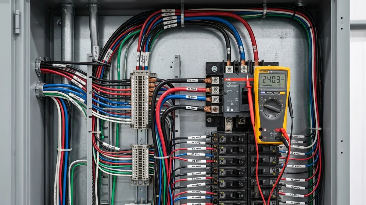
Circuit Voltage Drop & Return Path Architecture
Visualizing electrical potential drop from the supply panel through 75 ft of 12 AWG Copper conductors to the load terminals.
Understanding Voltage Drop in Electrical Circuit Design
Voltage drop is the reduction in electrical potential between a power source and connected equipment as current flows through circuit conductors. While copper and aluminum are effective conductors, every physical wire possesses finite internal resistance.
Under Ohm's Law (V = I × R), current traversing conductor resistance converts electrical energy into heat. This loss reduces the usable terminal voltage delivered to connected equipment.
Why Circuit Distance and Load Current Multiply Losses
Conductor resistance scales directly with physical distance. For example, running a feeder 150 feet produces three times the resistance of a 50-foot run of identical wire.
Voltage drop also scales directly with load current. When long distances combine with high currents, severe voltage loss can degrade motor performance, dim lighting, trigger electronic lockouts, or overheat conductors.
One-Way Physical Distance vs Complete Return Path
Electricians measure the one-way linear distance from the panel to equipment. However, electric current requires a complete closed loop to flow.
In two-wire DC and single-phase AC systems, current flows out along the supply wire and back along the return conductor. The formula applies a multiplier of 2 to cover both circuit legs.
Three-Phase Balanced Circuits and the √3 Multiplier
In balanced three-phase systems, currents in the three phase conductors are 120 degrees out of phase. Because their balanced vector sum at the neutral point equals zero, neutral conductors carry zero net return current under balanced conditions.
Line-to-line voltage drop between phase conductors is calculated by multiplying phase current by the line factor of √3 (approximately 1.73205), rather than the factor of 2 used in single-phase circuits.
Conductor Material: Copper vs Aluminum Resistance
Copper features an electrical resistivity of approximately 1.68 × 10⁻⁸ Ω·m, while aluminum presents approximately 2.82 × 10⁻⁸ Ω·m at standard temperatures. For the same AWG size, aluminum conductor resistance is roughly 1.6 times higher than copper.
Consequently, aluminum circuits typically require stepping up one to two trade wire sizes (for example, using 2 AWG aluminum instead of 4 AWG copper) to achieve equivalent voltage drop and ampacity.
National Electrical Code (NEC) Informational Notes on Voltage Drop
The National Electrical Code (NFPA 70) addresses voltage drop primarily through advisory Informational Notes rather than mandatory blanket rules. These non-mandatory guidelines help engineers balance installation cost against operational efficiency.
NEC Section 210.19(A) Informational Note No. 2 and Section 215.2(A)(1) recommend limiting voltage drop to 3% on the furthest branch circuit or feeder. Total combined drop across feeder and branch circuits should not exceed 5%.
Why Voltage Drop Alone Does Not Determine Conductor Ampacity
Conductor sizing requires satisfying two independent criteria: ampacity thermal limits and voltage drop limits. Conductor ampacity (NEC Section 310.16) defines the maximum continuous current a wire carries safely without insulation overheating. Ambient temperature and conduit fill adjustments directly derate this allowable ampacity.
A short 10-foot circuit might calculate a negligible 0.5% voltage drop, yet remain dangerously undersized if current exceeds allowable ampacity. Safe branch circuit design requires verifying both thermal ampacity and voltage drop limits independently.
Voltage Drop Calculation Formulas
The mathematical formulas used to calculate circuit loop resistance, voltage drop, percentage loss, and receiving terminal voltage across DC, single-phase, and balanced three-phase systems.
Variables & Constants
I (Amperes (A))L (Feet (ft))R (Ohms per 1,000 ft (Ω/kft))V_source (Volts (V))Multiplier (Unitless)- Resistance values reflect stranded conductors at 75°C (167°F) based on NEC Chapter 9 Table 8.
- Distances are entered as one-way measurements. The formula accounts for the return conductor path automatically.
- Three-phase calculations assume balanced loads across all three phases.
- This resistance-based model does not account for AC inductive reactance or load power factors.
Step-by-Step Worked Example: 120V Single-Phase AC Branch Circuit (16A, 75 ft, 12 AWG Copper)
Single-phase circuits require current to flow through both the ungrounded conductor and the return neutral. From NEC Chapter 9 Table 8, 12 AWG stranded copper has an internal direct-current resistance of 1.98 Ohms per 1,000 feet at 75°C.
Multiplying one-way distance in thousands of feet by the circuit multiplier and conductor resistance gives the combined loop resistance for the complete electrical circuit.
By Ohm's Law, current flowing through circuit loop resistance causes a potential drop of 4.752 Volts between the breaker panel and the load.
Dividing voltage loss by the nominal supply voltage shows a 3.96% drop, which exceeds the commonly referenced 3% branch circuit threshold.
The connected equipment receives 115.25 Volts at its terminals under steady 16-Amp operating current.
Voltage Drop Sizing Assumptions & Variables
Core technical assumptions, conductor properties, and mathematical baselines used in the voltage drop calculation engine.
| Parameter | Model Default | Typical Field Range | Practical Impact |
|---|---|---|---|
| Conductor Resistance Baseline | NEC Chapter 9 Table 8 (75°C Stranded) | Standard trade AWG / kcmil sizes | Calculations use stranded copper and aluminum resistance values from NEC Chapter 9 Table 8 at a 75°C (167°F) reference temperature. Operating conductors at lower temperatures (such as 25°C or 60°C) exhibits slightly lower resistance, while elevated ambient temperatures increase resistance. |
| Circuit Multiplier & Return Path | 2 for DC & 1-Phase AC | √3 (1.732) for 3-Phase AC | Two-wire complete loop or balanced 3-phase line-to-line | DC and single-phase calculations automatically account for outgoing and return conductors using a factor of 2. Balanced three-phase calculations use the line-to-line multiplier of √3 under the assumption of balanced phase currents. |
| Mathematical Model Scope | Resistance-Based Direct-Current & AC Model | Unity power factor / direct-current resistance | This version implements a pure resistance-based model. AC inductive reactance (NEC Chapter 9 Table 9) and load power factor can cause additional voltage drop in large conductors (such as 1/0 and larger) and long commercial conduits. |
| Comparison Threshold | 3% (User Configurable) | 1% to 5% typical planning ranges | The 3% and 5% values reflect common engineering guidelines and NEC informational notes for reasonable efficiency. They do not constitute universal mandatory code limits. |
Voltage Drop Frequently Asked Questions
What is voltage drop?
How do you calculate voltage drop?
Is voltage drop calculated using one-way or round-trip distance?
Why is voltage drop more significant on 12V systems?
How does wire gauge affect voltage drop?
When is √3 used in voltage drop calculations?
What does the NEC say about voltage drop?
Preliminary Planning & Electrical Engineering Disclaimer
- This calculator provides preliminary electrical calculations based on simplified mathematical models and user-supplied parameters. It does not constitute professional engineering advice, electrical inspection approval, or installation sign-off.
- Voltage-drop analysis does not replace conductor ampacity verification, overcurrent protection device sizing, insulation temperature ratings (60°C, 75°C, 90°C), ambient temperature derating, conduit fill adjustments, terminal lug temperature limitations, or local electrical code compliance.
- Working on electrical wiring, distribution panels, and high-energy circuits involves substantial risk of electrical shock, arc flash, personal injury, and fire. Always consult a qualified licensed electrician or electrical engineer to verify physical conductor sizing, overcurrent protection, and installation compliance.
Related Electrical & Solar Calculators
Watts to Amps Electrical Calculator
Convert real power in Watts to circuit current in Amperes across DC, 120V/240V single-phase, and balanced three-phase systems.
Amps to Watts Electrical Calculator
Calculate real power (W) and apparent power (VA) from circuit amperage and voltage for DC and AC equipment.
Three Phase Power Calculator
Calculate 3-phase real power (kW), apparent power (kVA), and line current across balanced circuits.
Solar Battery Sizing Calculator
Size off-grid and backup battery storage capacity in Amp-hours and Watt-hours based on daily energy consumption.
Solar Charge Controller Calculator
Determine MPPT and PWM controller sizing based on PV array wattage, battery bus voltage, and cold-weather open-circuit voltage.
15-Amp vs 20-Amp Circuit Wattage Guide
Learn safe breaker capacity, the NEC 80% continuous load rule, and 14 AWG vs 12 AWG wire sizing limits.
Solar Panels in Series vs Parallel Guide
Learn how series and parallel solar panel wiring affects circuit voltage, current, wire size, and line losses.
Solar System Size Calculator
Calculate the solar system size in kW and approximate panel count required to power your home based on monthly kWh electricity consumption.